Assalamualaikum Everyone. I am @imranhassan From #Bangladesh
![Untitled design (2).png] (https://cdn.steemitimages.com/DQmZkSqjH8Zdnyp3SeCw2JMswASUz2MCa6twwoqyW4AkDF8/Untitled%20design%20(2).png)
| Functionality of the components used in this diagram. |
|---|
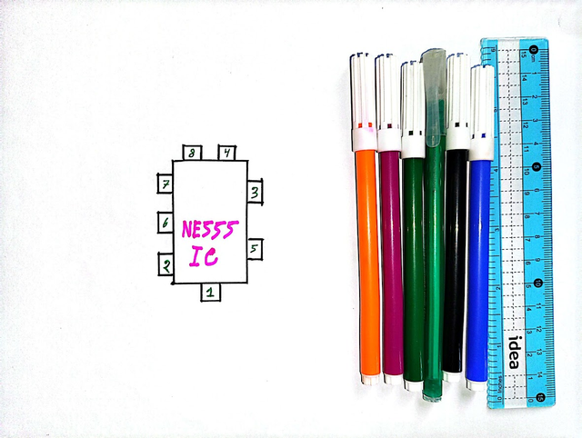
NE555 Timer IC.
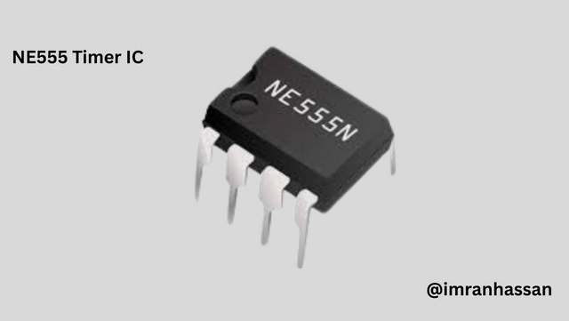
This is a timing chip, which helps to light the LED in a specific rhythm.
SL100 Transistor.
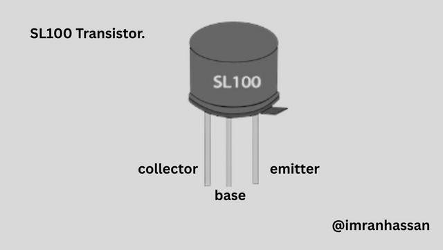
It works like a switch. It controls which side the output will go to in the circuit.
LED red.
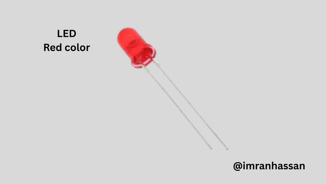
Used to show light. Indicates the direction when turning left or right.
SPDT Switch.
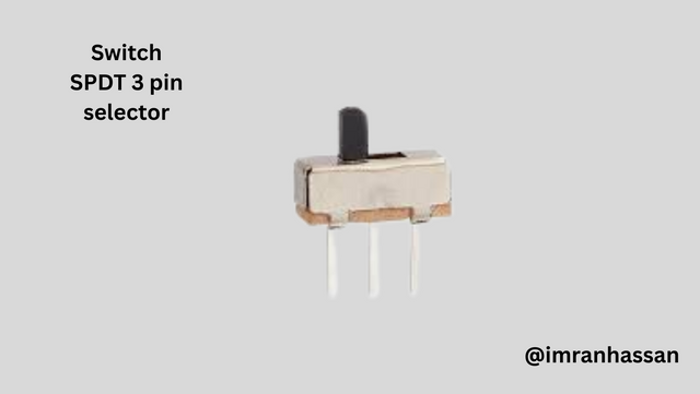
The switch helps to select — left or right — which side LED will light.
Electrolytic Capacitor 33 µF.
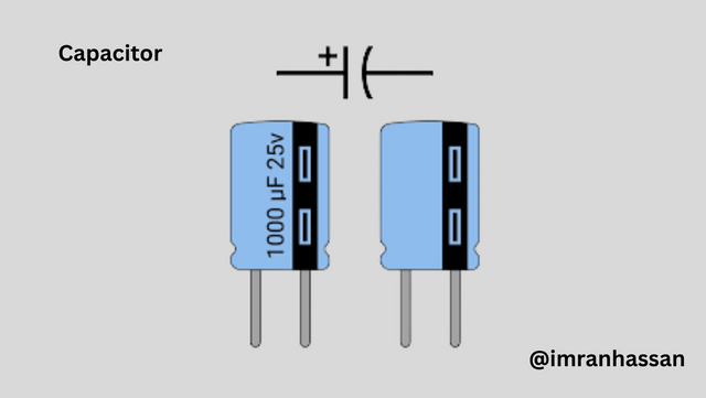
Keeps the signal inside the circuit stable and creates some delay.
Ceramic Capacitor 0.1 µF.
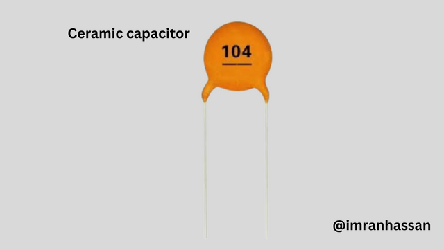
Works as a light filter and spike removal, so that the circuit works smoothly.
Resistors: 100Ω, 10KΩ, 220Ω.
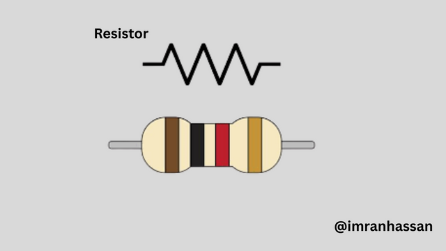
Controls the current so that the LED or other parts are not damaged.
| Step 1: IC pinout. |
|---|
 |
|---|
First, I took all the pins of the NE555 IC. I wrote each PIN number clearly so that it is easy to connect later. I also took a picture with the necessary pen and scale next to it. And I am arranging the pin-out below; which one does what?
| Step 2: Power and reset connection. |
|---|
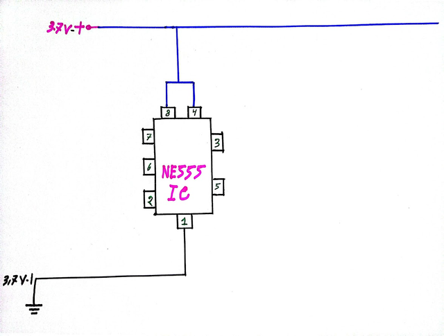 |
|---|
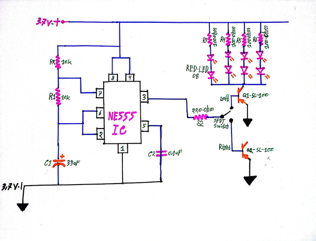
In the second step, first I gave a 3.7-volt positive line to pin number 8. Then I connected pin number 4 to pin number 8 so that the circuit does not reset while it is on. And I connected pin number 1 to ground.
| Step 3: Timing part connection. |
|---|
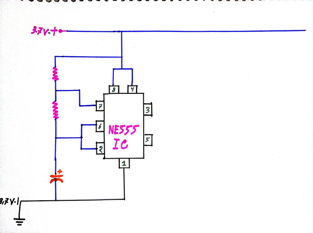 |
|---|
Then I placed two 10 kilohm resistors from pin number 7. I also connected the resistors to pins number 6 and 8. Then I placed a capacitor between pins number 6 and 2. This part works to create timing.
| Step 4: Output and control connection. |
|---|
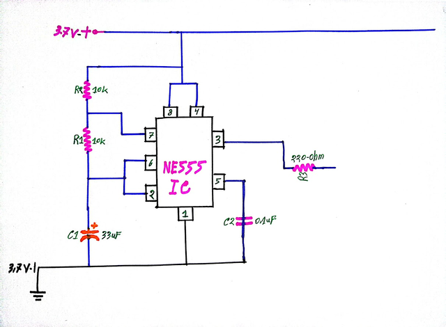 |
|---|
Then I connected a 0.1 microfarad capacitor to pin number 5 so that the circuit works stably. Then I took the output from pin number 3 and used a 220-ohm resistor there.
| Step 5: Switch and output control. |
|---|
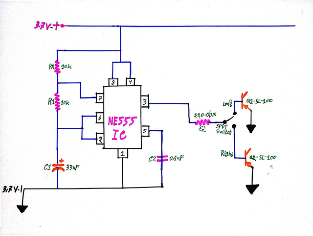 |
|---|
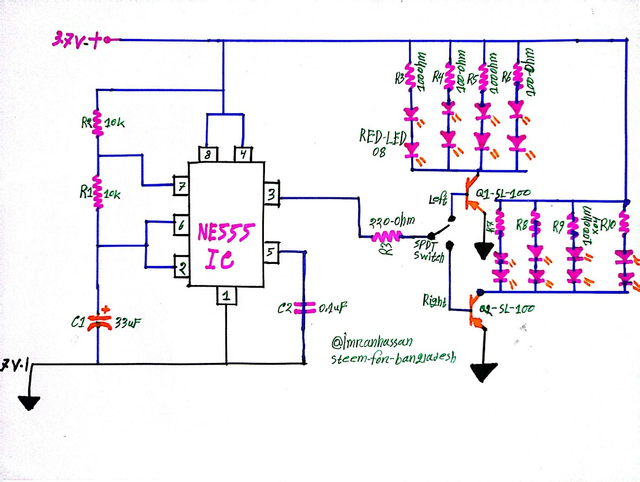
Then I connected the output line of pin number 3 to an SPDT switch with a 220-ohm resistor. Through this switch, I can separately select the left and right directions. Then I installed two SL100 transistors on either side — one for the left output, the other for the right output.
| Step 6: LED Connections. |
|---|
 |
|---|
Then I installed four 100-ohm resistors across the output of transistor Q1 on the left. Then I connected two red LEDs to each resistor. A total of 8 LEDs were installed.
| Step 7: LED Connections on the Right. |
|---|
 |
|---|
Then I installed four 100-ohm resistors across the output of transistor Q2 on the right. Two red LEDs were connected to each resistor. A total of 8 LEDs were installed here as well.
| Proof of my hand-drawn circuit. |
|---|
 |
|---|
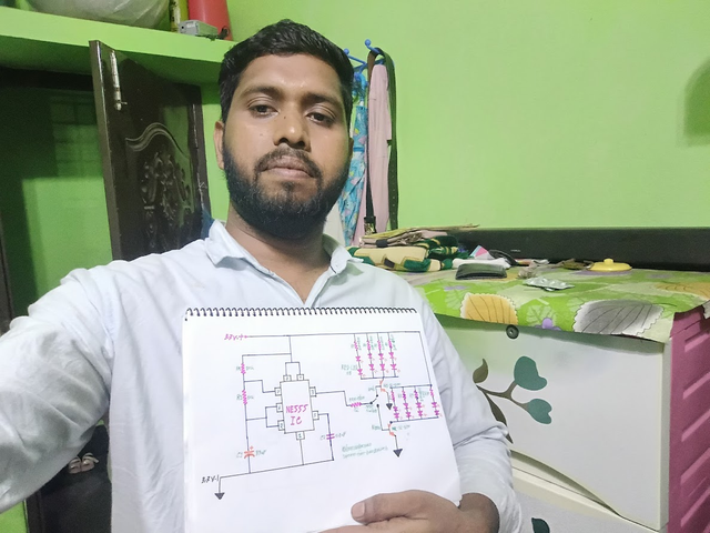
I took a selfie with my hand-drawn circuit diagram. Below I wrote my username and community name to prove that this is my own work.
| Conclusion. |
|---|
Today I made a direction indicator light for a bicycle. In this circuit, I have used an NE555 timer IC to show left and right direction by flashing an LED. I have made the entire circuit step by step by hand drawing. This is a simple but learning project.
| Materials used in this circuit diagram. |
|---|
| Sr. No. | Part name | Value | Quantity |
|---|---|---|---|
| 1. | IC | NE555 Timer | 1 piece |
| 2. | NPN transistor | SL100 | 2 pieces |
| 3. | LED | Red color | 16 pieces |
| 4. | Switch | SPDT 3 pin selector | 1 piece |
| 5. | Electrolytic capacitor | 33µF | 1 piece |
| 6. | Ceramic capacitor | 0.1µF | 1 |
| 7. | Resistors | 100Ω × 8, 10KΩ × 2, 220Ω × 1 | Total 11 |
| 8. | battery | 3.7-volt | 1 |
.gif)
| Photography Details | 📱 Device: Walton Xanon90 | 📍 Location: Narayanganj, Bangladesh | 📷 Captured By: @imranhassan |
|---|
https://x.com/ImranHosen98536/status/1938249432077897922
Downvoting a post can decrease pending rewards and make it less visible. Common reasons:
Submit
Your content has been successfully curated by our team via @ ngoenyi.
Thank you for your valuable efforts! Keep posting high-quality content for a chance to receive more support from our curation team.
Downvoting a post can decrease pending rewards and make it less visible. Common reasons:
Submit
Hi, Greetings, Good to see you Here:)
Downvoting a post can decrease pending rewards and make it less visible. Common reasons:
Submit