Assalamualaikum Everyone. I am @imranhassan From #Bangladesh
.png)
| What is the function of this circuit? |
|---|
The main objective of this project is to make a timer where a buzzer will sound for a specific time when a button is pressed. This time can be adjusted by yourself with a variable resistor. It does not require any microcontroller or programming. It can be used in alarms, countdowns, or any other time-based sound system.
| Initial preparation |
|---|
 |
|---|
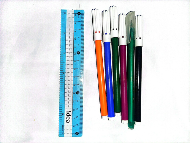
First, I took a white paper and used some coloured gel pens and scales to draw the circuit. Different colours have been used to make each connection in the circuit clear and easy to understand.
| Components used and their functions |
|---|
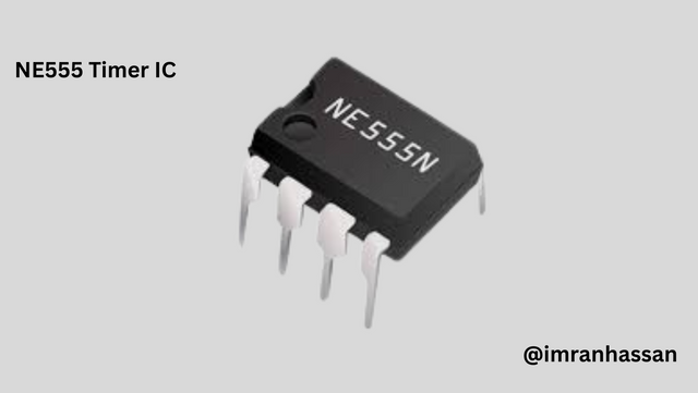
🔹 IC NE555 Timer (IC1)
 |
|---|
Usage: This is a timer IC that generates a signal in the circuit and provides output for a specific time.
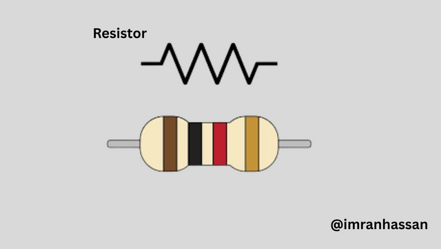
🔸 Resistor
 |
|---|
Usage: Helps in controlling the timing signal.
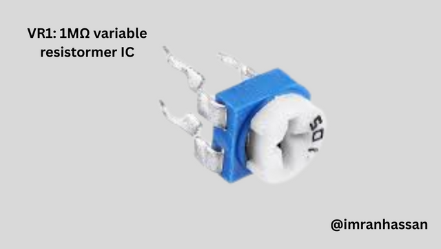
🔹 VR1: 1MΩ variable resistor
 |
|---|
Usage: Used to adjust the timing.
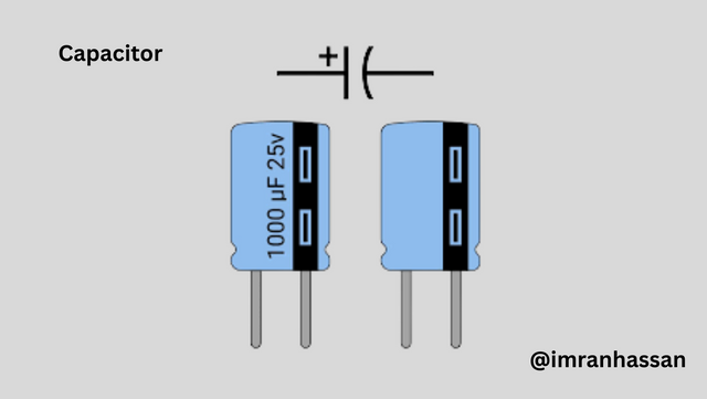
🔸 C1: 1000µF, 16V capacitor
 |
|---|
Usage: Holds charge and maintains the stability of the circuit.
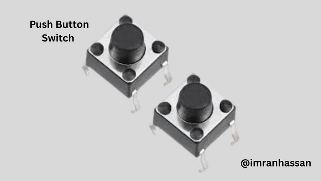
🔹 Push Button Switch
 |
|---|
Usage: A button that is pressed by hand to activate the circuit.
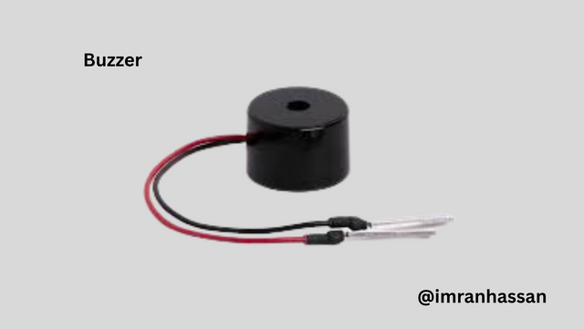
🔸 Buzzer (9V)
 |
|---|
Usage: Output device of the circuit, which produces sound for a certain period of time.
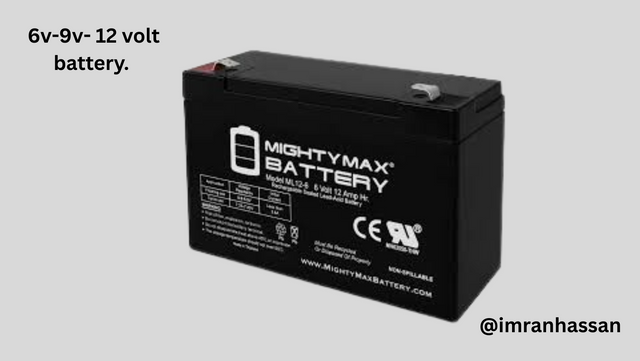
🔹 Battery: 9V
 |
|---|
Usage: Provides power to all parts of the circuit.
| 🔹 Step 1: Installing 555 IC and connecting power |
|---|
In the first step of making the circuit, I take the popular NE555 Timer IC in my hand. This IC is the main controlling device of the entire circuit, through which the timing control and output are determined. I carefully isolate the 8 pins of the IC and clearly mark each pin number. Then I make negative and positive connections of the battery to the IC.
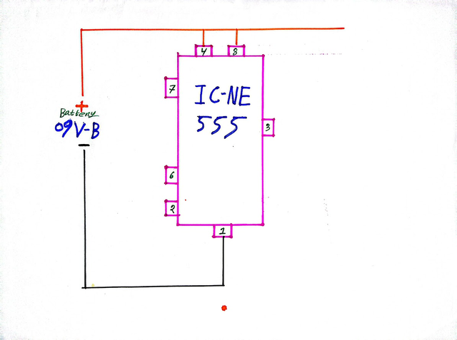 |
|---|
Pin 1 (GND): This pin is connected to the negative line of the battery, which acts as the ground of the IC.
Pin 8 (VCC): This pin is connected to the positive line of the battery, through which power is supplied to the IC.
Pin 4 (Reset): This pin is also connected to the positive line so that the circuit does not reset unexpectedly and works stably.
In this step, I have not added any additional components (such as resistors or capacitors). I have only completed the grounding of the IC and the power connection. This grounding prepares the circuit for the next step.
| 🔹 Step 2: Connecting the timing control components |
|---|
In this step, I have added three components that are important in determining the timing of the circuit: a fixed resistor, a variable resistor (VR), and a push button. The circuit's functionality is ensured by ensuring the correct connection of each component.
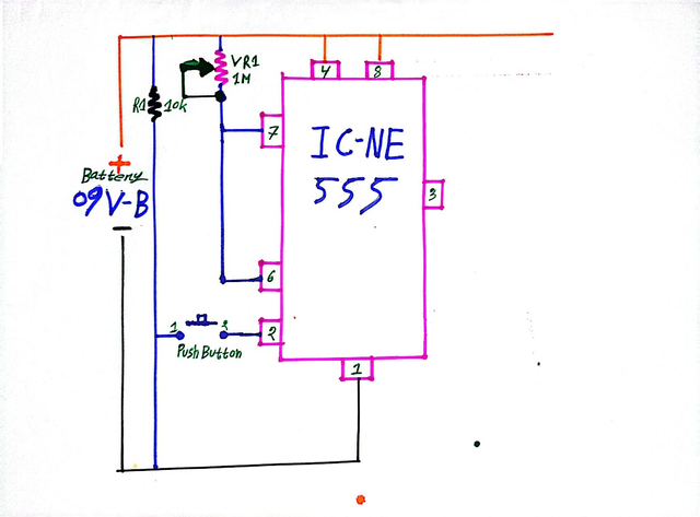 |
|---|
🔹 R1 (10 kΩ resistor): A 10 kilo-ohm resistor is connected between Pin 7 (Discharge) and the positive line. This resistor controls the current of the timing signal in the circuit and maintains reliability.
🔹 VR1 (1MΩ Variable Resistor): A 1 mega-ohm VR is connected between Pin 7 and the VCC line. This variable resistor can be used to increase or decrease the length of time. This is the key element to make the circuit "adjustable".
🔹 Push Button Switch: A push button is connected to Pin 2 (Trigger). When it is pressed, the circuit is activated and the timing starts. The other end of the button is connected to the negative line of the battery.
🔹 Pin 6 and Pin 2 Connection: Pin 6 (Threshold) and Pin 2 (Trigger) are connected together so that the timing interval starts and ends reliably.
By completing this step, the timing control part of the circuit is complete. In the next step, we will add the output unit.
| 🔹 Step 3: Capacitor Connection and Output Device Addition |
|---|
In this step, I have completed two important connections in the circuit:
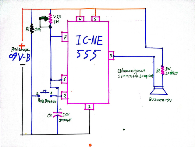 |
|---|
🔸 C1 (Capacitor 1000µF, 16V): A 1000µF capacitor has been connected between Pin 6 and the Ground (GND) line. It helps in maintaining the timing interval and stability of the circuit by holding the charge.
🔸 Pin 3 → Buzzer & R2 Connection: The output signal from Pin 3 (Output) is first connected to a 1W, 10Ω resistor (R2), and then it is connected to the 9V Buzzer.
The addition of this resistor is an important safety measure.
Protects against excessive current flowing directly into the buzzer
Maintains the load balancing of the circuit
Increases the lifetime of the buzzer
As a result, Pin 3 → R2 → Buzzer → Ground – this entire output chain is now successfully completed. In this step, we have successfully created the final output part of the circuit. Now the circuit is ready – the buzzer will sound for a specific time when the button is pressed.
| ✅ Conclusion |
|---|
 |
|---|
This circuit is a very effective and simple adjustable timer project. With just a single push button, we can keep the buzzer on for a specific time. The whole project is ideal for new students — because it can be learnt through hand-drawn diagrams on one hand, and the timing concept can be practically understood on the other.
.gif)
| Photography Details | 📱 Device: Walton Xanon90 | 📍 Location: Narayanganj, Bangladesh | 📷 Captured By: @imranhassan |
|---|
Thank you for sharing on steem! I'm witness fuli, and I've given you a free upvote. If you'd like to support me, please consider voting at https://steemitwallet.com/~witnesses 🌟
Downvoting a post can decrease pending rewards and make it less visible. Common reasons:
Submit
Your content has been successfully curated by our team via @ kouba01.
Thank you for your valuable efforts! Keep posting high-quality content for a chance to receive more support from our curation team.
Downvoting a post can decrease pending rewards and make it less visible. Common reasons:
Submit