Assalamualaikum Everyone. I am @imranhassan From #Bangladesh
.png) |
|---|
This is basically a security circuit, where the alarm sounds when the laser light is turned off. In the circuit, I have used a 555 timer IC and will detect the cutting of the laser line through the LDR sensor. This circuit can be used in the door of the house, a table drawer or any small secure place. I have drawn the circuit by myself step by step so that even beginners can understand it easily.
| Function of the components used. |
|---|
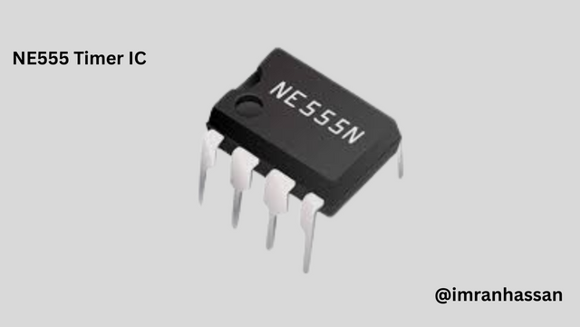
555 Timer IC:
 |
|---|
Used to generate timing signals.
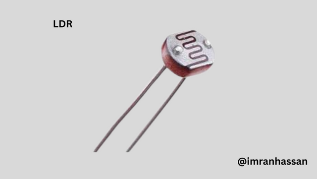
LDR:
 |
|---|
The signal changes when the light decreases.
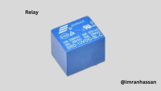
Relay:
 |
|---|
Transfers the low-voltage signal to the high-voltage device.
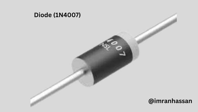
Diode:
 |
|---|
Blocks the reverse current coming from the relay.
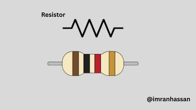
Resistor:
 |
|---|
Controls voltage and current.
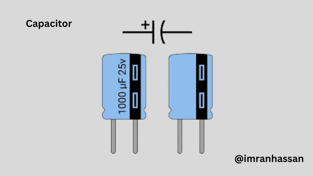
Polar Capacitor 1000 µF:
 |
|---|
Keeps the signal stable and fixes the timing.
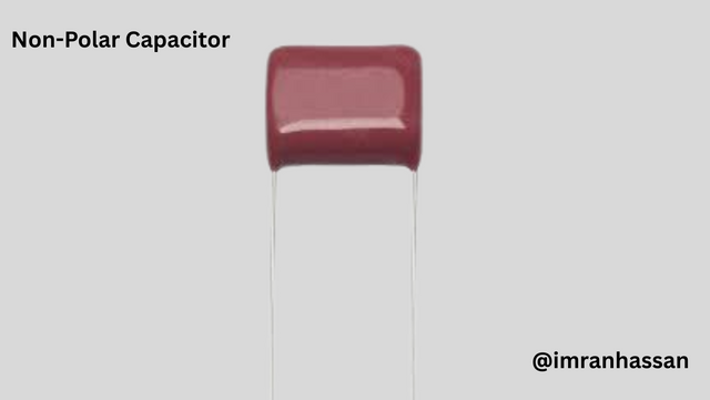
Non-Polar Capacitor 0.22 µF, 10 nF:
 |
|---|
Helps filter small spikes.
| Step 1: Use notebook and colored pen. |
|---|

I used coloured colouring pens to clearly explain the diagram of this circuit on a white paper so that each connection can be clearly seen.
| Step 2: IC connection. |
|---|
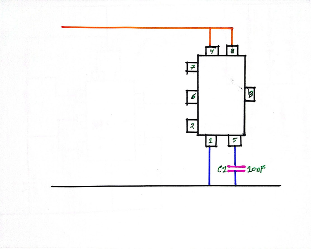
I gave a positive line to pin number 8 and took pin number 1 to ground. Then I placed a 10 nF capacitor on pin number 5 so that the circuit works stably.
| Step 3: Timing part connection. |
|---|
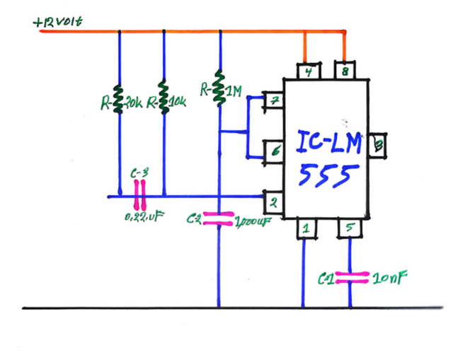
I connected 1 megaohm resistor to pin number 6 and 2. Then I placed 20K and 10K resistors on the top. I placed 0.22µF and 1000µF capacitors on the bottom so that the signal works properly.
| Step 4: Sensor and Transistor Connection. |
|---|
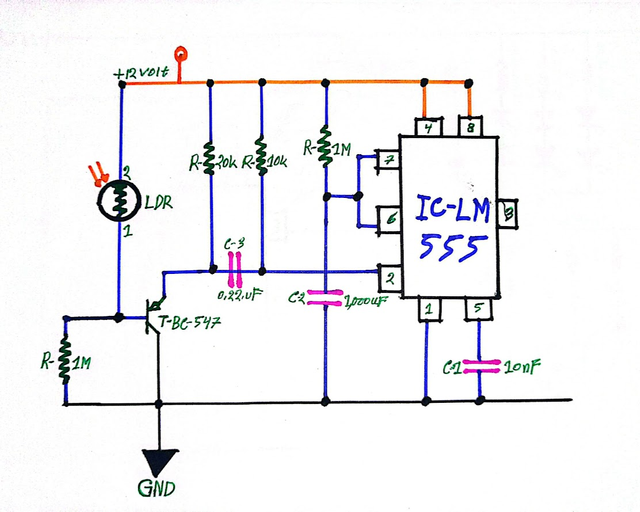
I have connected the LDR to the 12-volt line. Then I have connected a 1 megaohm resistor and a BC547 transistor below. The circuit can generate a signal when the light is cut.
| Step 5: Laser, Relay and Bell Connection. |
|---|
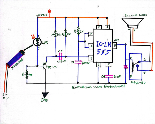
I have connected the laser light in front of the LDR. Then I have connected a 12-volt relay and a buzzer to the output line. When someone cuts the laser, the relay is activated and the alarm sounds.
| My Proof |
|---|
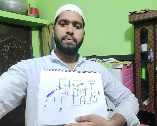
After finishing the art I have drawn by hand, I have written my username and community name below. Then I have taken a selfie to prove that I did the work myself.
| Conclusion |
|---|
I have made this laser alarm circuit very easily. When the light is cut, the alarm sounds, so it can be used for small security purposes. I have drawn everything by myself and made it step by step so that even beginners can easily understand.
List of used parts
| S.no | Components | Value | Qty |
|---|---|---|---|
| 1. | Resistor | 10k, 1M | 2, 2 |
| 2. | Diode | IN4007 | 1 |
| 3. | Polar Capacitor | 1000µF | 1 |
| 4. | IC | 555 Timer | 1 |
| 5. | Relay | 12v | 1 |
| 6. | Non-Polar Capacitor | 0.22µF, 10nF | 1, 1 |
| 7. | Jumper Wire | 1 | |
| 8. | LDR | 1 |
.gif)
| Photography Details | 📱 Device: Walton Xanon90 | 📍 Location: Narayanganj, Bangladesh | 📷 Captured By: @imranhassan |
|---|
https://x.com/ImranHosen98536/status/1938794806505021604
Downvoting a post can decrease pending rewards and make it less visible. Common reasons:
Submit
Our team is looking for quality posts and comments to reward across the steemit platform. Enhance your experience in creating engaging content
Curated by@𝗁𝖾𝗋𝗂𝖺𝖽𝗂
Downvoting a post can decrease pending rewards and make it less visible. Common reasons:
Submit